| Version 2 (modified by dc, 12 years ago) (diff) |
|---|
BarrettHand BH8-280/282 Lubrication
Each BarrettHand™ unit has been lubricated and tested prior to shipping. Periodically, lubrication must be reapplied to areas with high probability of lubricant flow. Use the grease syringe to apply Mobil 1® Synthetic Grease (both included with the maintenance kit) to all exposed gear teeth at the application points according to Figure 14 and the schedule in Table 6.
Table 6 - Lubrication Schedule
| Application Point | Maintenance Cycle |
| Finger Worm Gears | 5000 cycles |
| Finger Spur Gears | 5000 cycles |
| Finger Motor Spur Gears | 5000 cycles |
| Palm Spur Gears | 5000 cycles |
Figure 14 - Lubricant Application Points
Lubricating the finger spur gears requires caution, because you must remove each finger from the palm assembly to access this application point. See the section below on how to detach, lubricate, and reattach the finger.
Finger Replacement
Read all steps below before conducting this maintenance. Pogo pins that connect to sensors in the hand may shear unless the finger is detached and reattached with care. It is best to lubricate only one finger at a time.
Step 1: Turn off power to Hand.
Step 2: Open all fingers on the BarrettHand and open the Spread completely (fingers 1 and 2 opposite finger 3). The fingers can be opened manually using a 2 mm hex wrench in the right-hand hole shown. See Figure 15.
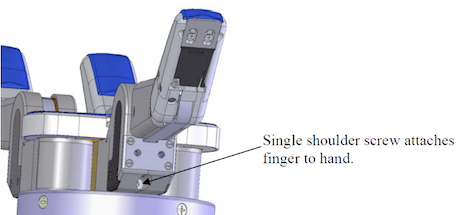
Step 3: Locate shoulder screw that connects the finger to the hand. See Figure 16.
Step 4: Using a 2 mm hex wrench, unscrew the shoulder screw. Turn the hand sideways and slap the base of the BarrettHand with your palm to get the shoulder screw to fall out.
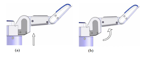
Step 5: Slide the finger assembly up slightly (Figure 17a), then pivot it out (Figure 17b).
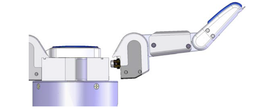
If the joint-torque sensor option is installed, BE CAREFUL not to damage the gold-plated electrical contact pins when disengaging the teeth. Do not twist or rock the finger when removing or attaching it.
Step 6: Slowly pull finger away from the motor body.
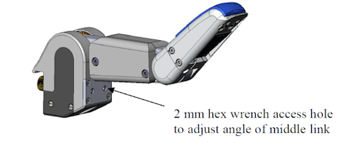
Step 7: Take the replacement finger and verify that the inner link is driven into its stop. Using a 2 mm hex wrench, insert it into the right-hand hole and rotate counter-clockwise until the finger stops moving. See Figure 19.
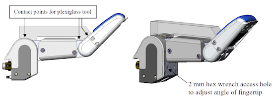
Step 8: Check/adjust the angle of the fingertip using the plexiglass finger-angle tool. Place the tool as shown (Figure 20). Using a 2 mm hex wrench, insert it into the left-hand hole and rotate until the finger stops up against the forward edge of the plexiglass tool.
For BH8-262 hands only: Should either link, or the spur gears to which they are attached, move after the finger has been removed, the fingertip position must be reset. Use a 2-mm hex wrench to manually rotate the Joint-3 drive 5 1/2 revolutions from the position where both links are inline and horizontal.
Step 9: If necessary, add Mobil 1® Synthetic grease to the motor body cavity using the syringe provided. Cover all gear teeth with a thick bead of grease. Reverse Steps 5 and 6 to attach the new finger. Be careful not to damage (shear) the electrical ÒpogoÓ pins at the base of the motor (Figure 21).
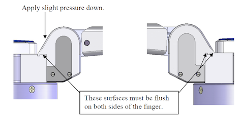
Step 10: Once the finger is in place, apply slight pressure down and screw in the shoulder screw. See Figure 22.
Step 11: Verify that the finger operates smoothly. Using a 2mm hex wrench in the right-hand hole (see Figure Error: Reference source not found), drive the finger manually through its range of motion.
Finger replacement is complete.


