| Version 3 (modified by cv, 14 years ago) (diff) |
|---|
WAM Hardware Setup
Mounting
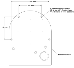
The mounting-surface for the WAM should be designed to handle the large reaction forces generated at the base of the arm during high-acceleration operation. The WAM can be fastened to a prepared mounting-surface in several ways. If you use four M10 or 3/8” screws, remove the base cover to access the four bolt holes in the base plate. The holes are located on the base of the WAM according to Figure 18 and Figure 19. The plate thickness is 8mm. If you use M12 screws, you can screw upwards from the opposite direction, eliminating the need to removing the base cover. Alternatively, the WAM can be mounted using the clamps provided in the maintenance kit. It is important that the mounting surface NOT be grounded to earth ground (see “Grounding” section below).
Grounding
Grounding of all hardware must be considered when locating the WAM and its peripherals. Multiple grounding paths between the external power supply, the WAM chassis, the Barrett Hand power supply, an external computer and earth ground can cause internal communications problems. It is important to mount the WAM itself on a non-grounded surface. However, if you need to physically mount it to a grounded structure (upside-down to a grounded I-Beam, or mounted to a grounded metal table, for example) contact Barrett Technology for instructions on making a slight modification to the external wiring to avoid multiple ground paths. Additionally, it is preferable that the metal chassis of the External Power Supply, the metal chassis of the Barrett Hand Supply (if applicable) and the WAM chassis are not in electrical contact with each other. If this is not possible, contact Barrett Technology for instructions. Finally, if using an external computer connected to either the WAM through the CANBus or the external Barrett Hand Supply, the computer should be grounded. Again, contact Barrett if this poses a problem. A computer connected to the Ethernet port can either be grounded or not grounded.
WAM Wrist (Optional)
To avoid damaging the WAM electronics, please make sure the WAM is powered off before detaching or attaching any outer link. In addition, if the Wrist was shipped separately from the WAM, a Safety Termination will be attached to the base connector of the Wrist, and must be removed before mounting the Wrist. If the Wrist is ever removed from the WAM, ensure that the Safety Termination is attached as soon as the Wrist is disconnected to prevent damage to the Wrist Pucks.
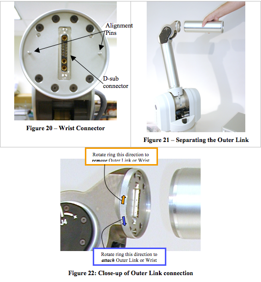
Figure 21 shows that the outer link can be unscrewed and removed from the WAM to accommodate the WAM Wrist (if the 7-DOF WAM is purchased). After removing the outer link, connect the WAM Wrist:
- Align the D-sub connector of the Wrist with the mating connector on the end of the “elbow” of the WAM such that both have the same orientation.
- Connect the alignment pins on the end of the elbow with the mating connections on the Wrist.
- Thread the quick-connect ring onto the wrist base.
No special wrenches, fasteners, or tools are required, however, it may be necessary to shake the outer link (or Wrist) gently back and forth while tightening or loosening the ring. This ring should only be hand-tightened. It is normal for there to be a small number of threads left when fully tightened. This single operation also makes all electrical connections to the WAM Wrist. Figure 20 shows the electrical connector at the end of the WAM.
Safety Board Settings
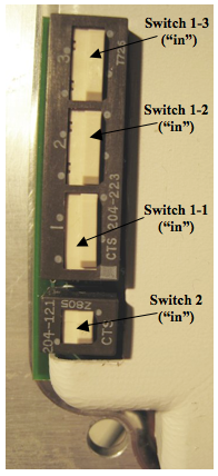
For different methods of communication (and different connections to the BarrettHand™, if attached) certain switches must be changed. To access these switches, turn off the WAM™, remove the 4-mm Hex screw in the upper-left corner of the back of the WAM™ (Figure 24), unlatch the base cover, and rotate the back plate of the WAM™ out so that it is in a horizontal position. (Figure 25). If you are facing the WAM™ from the back, the relevant switches will be on the lower-left corner (see Figure 23). If a switch is “out” the raised part of that pin is on the side closest to the edge of the safety board, and the opposite is true if the switch is “in”.
Table 1 – WAM Communication Settings
| Mode*: | Switch 1-2 | Switch 1-3 |
| Ethernet | IN | IN |
| CAN (from External PC) | OUT | OUT |
Table 2 – Hand Communication and Power Settings
| Modes*: | Switch 2 | Switch 1-1 |
| Internal Power & Communications | IN | IN |
| External Power & Communications | OUT | OUT |
Figure 23 – Safety Board Switches
Electrical Connections
Power Source
For applications using a standard (50-60 Hz, 100-120 or 200-240V) AC outlet:
- Place the Power Supply on a flat, secure surface and verify that the Power Supply is OFF.
- Attach the Power Supply Line Cord into any convenient outlet and also into the corresponding Power Supply socket.
- Attach the DC power cable from the socket on the back of the Power Supply to the socket on the WAM labeled “DC Power”, as shown in Figure 11. Tighten the strain-relief screws on both ends of the cable using the screwdriver provided in the maintenance kit.
For mobile applications or applications that require alternate DC power sources, simply connect the DC power cable directly from the power source to the socket on the WAM labeled “DC Power” as shown in Figure 26 (see Table 3 for details on DC power requirements). Tighten the strain-relief screws using the screwdriver provided in the maintenance kit.
Table 3 – DC Power Requirements
| Status | Control | 4-DOF | 7-DOF |
| Powered on, no torques | External | 18 W | 27 W |
| Active at home position | External | 30 W | 40 W |
| Active at worst-case** position, 4kg payload | External | 65 W | XXX |
| Active at worst-case** position, 3kg payload | External | XXX | 80 W |
| Active at worst-case** position, 3kg payload | Internal | XXX | 85 W |
| Active at worst-case** position with BH8-280, 2kg payload | Internal | XXX | 120 W |
| Peak | External | 600 W | 800 W |
** The worst-case position is the arm fully extended, with the base rotated 90 degrees such that joints 2, 4 and 6 must exert a large torque to counteract gravity.
Pendants
Of the two pendant cables, connect the pendant box with three colored buttons and a red E-Stop to the socket on the WAM marked “Pendant - Control”. Connect the other pendant box (with only a red E-Stop) to the socket on the WAM marked “Pendant - Display”. See Figure 27 for both pendants. Tighten the strain-relief screws using the screwdriver provided in the maintenance kit.
Communications
You can control the WAM over wired Ethernet, wireless Ethernet, or CANbus.
Wired/Wireless Ethernet
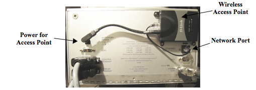
If you are using wired Ethernet to communicate between your personal computer and the internal WAM PC, attach the Ethernet cable from the network port on the WAM to a port on an Ethernet switch or hub. If you are using wireless Ethernet, connect the provided wireless access point (AP) to the network port of the WAM. When the WAM turns on, it will request an IP address from a DHCP server.
The provided AP will return an address of the form: 192.168.nnn.100, and the ssid of the AP is WAM-nnn, where nnn is the serial number of your WAM. You can use a laptop PC or other wireless-enabled device to connect to the AP. You can also log in and configure the AP by going to http://192.168.nnn.30. Username is “admin”, password is “WAM”. Once logged in to the AP, you can check the IP addresses assigned by DHCP by clicking on the “DHCP” button on the left-hand side of the web page. Your PC’s network name will be listed there, and there should be an entry without a name- that is the WAM PC and its corresponding IP address. This is the address you will use to control the WAM.
You may want to add a static entry for the WAM in your DHCP server to make future log-ins easier.
CANbus
If you are using the optional external PC, attach the CANbus cable from the socket on the WAM labeled “CAN” to the PC as shown in Figure 29. Either attach a monitor and keyboard to the PC to operate the PC directly or connect the PC to a personal computer with remote terminal software to operate the PC remotely. Tighten the strain-relief screws using the screwdriver provided in the maintenance kit.
Power-Up Sequence
Perform the following checks before powering up the WAM:
- If you are using Ethernet or CANbus communication, verify that the appropriate cable is plugged into the desired communications port.
- Confirm that the WAM safety board is properly configured for the communication option you have chosen.
- Verify that the Control and Display Pendant cords are plugged into the correct sockets on the back of the WAM.
- If you are using an AC power source, verify that the AC Line Cord is plugged into a valid power source and into the power outlet on the back of the Power Supply.
- If you are using the external WAM PC, verify that the computer line cord is plugged into a power source and into the power outlet on the back of the computer.
Once the previous steps are complete, your WAM is ready for start-up. Power up the system according to the instructions below:
- Turn on the power source to the WAM.
- If using the external PC, turn on the power source to the external PC.
- If using a personal computer to control the WAM, connect to the WAM PC (From a *nix PC, use ssh robot@<wam-ip-address>, or from a Windows PC, use the free PuTTY ssh client to connect – Putty can be downloaded at http://www.putty.nl/download.html –username = robot, password = WAM).
- Launch control program (btclient/src/btdiag/btdiag is standard)
- Make sure both E-Stop buttons are reset (up). If they are not, rotate them one quarter of a turn clockwise.
- Press <Shift+Reset/Idle> on the control pendant.
- Place the WAM into its home position.
- Press <Shift+Activate> on the control pendant.
The WAM is now ready for use.


